$51.93
$75.82
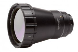
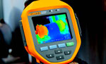
10 things you need to know about Thermal Imagers Whether you choose a simple point-and-shoot model or a high-end thermal imager with all the bells and whistles, here are some key features and specs you should consider: 1 Resolution Detector resolution indicates the number of detector pixels on the camera. More pixels, means higher resolution Spatial resolution is based on detector pixels and the field of view (FOV) spec, combining them to define the area the imager sees at any given moment. Spatial resolution can be used to help define the smallest object size that can be detected. A lower spatial resolution value means better detail and image quality 2 Focus With a variety of focus mechanisms to choose from, it is important to take into account your skill level as well as the application in selecting a focus type. Here are the common focus mechanisms: Fixed: Point and shoot simplicity Manual: Precise incremental focus Auto focus: Automatically focuses on a target but may require manual adjustment Laser-assisted auto focus: Uses a built-in laser distance meter to calculate distance to the target Multifocal: Captures and stores multiple images of the target from varying focal distances and uses software to blend them into one image with ultra-sharp depth of field detail. Fluke Corp., for example, calls its implementation of this technology MultiSharp™ Focus --> <!-- --> </div> </div> <div class="row-fluid"> <div class="span8"> <div class="row-fluid"> <div class="span2"><span class="number-breakdown">3</span></div> <div class="span10"> <h5 class="clear-m-b">Temperature range </h5> <p>The highest and lowest temperature you encounter in your inspection determines the temperature range you need from your thermal imager. Or, select a camera with a wide temperature range that automatically selects the range based on your scene, or allows you to manually select the temperature range.</p> </div> </div> <div class="row-fluid"> <div class="span2"><span class="number-breakdown">4</span></div> <div class="span10"> <h5 class="clear-m-b">Lens options</h5> <p>A camera that lets you change <a href="/category/fluke_lenses" target="_blank">lenses</a> increases your versatility, allowing you to inspect many more types of equipment and situations. There are lots of choices for lots of applications—standard, wide angle, telephoto, and macro.</p> </div> </div> <div class="row-fluid"> <div class="span2"><span class="number-breakdown">5</span></div> <div class="span10"> <h5 class="clear-m-b">Saving images and additional data</h5> <p>Save infrared and digital images and in some cases voice notes to internal memory, a removable SD card, or to a USB flash drive. It’s important to have the flexibility to save images and additional related data to different media for backup or sharing.</p> </div> </div> </div> <div class="span4 well"> <a href="/product/fluke-ti450-sf6-thermal-imager-with-gas-detection" target="_blank"><img src="/images/specialty-pages/fluke-pti-bonus-content/Ti450-SF6-gas-leak.png" class="" alt="TI450 thermal imager being used to check for gas leaks"/><p style="text-align: center; margin-bottom: 0px;"><small>TI450 SF6</small></p></a> </div> </div> <div class="row-fluid"> <div class="span8"> <div class="row-fluid"> <div class="span2"><span class="number-breakdown">6</span></div> <div class="span10"> <h5 class="clear-m-b">Color palettes</h5> <p>Slight differences are easier to see with a monochromatic palette, such as grayscale or amber. High contrast palettes can make it easier to quickly find obvious anomalies. You should be able to change the palette in the camera or in the software.</p> </div> </div> <div class="row-fluid"> <div class="span2"><span class="number-breakdown">7</span></div> <div class="span10"> <h5 class="clear-m-b">Color alarms</h5> <p>Use these to quickly highlight areas outside your normal temperature ranges.</p> </div> </div> <div class="row-fluid"> <div class="span2"><span class="number-breakdown">8</span></div> <div class="span10"> <h5 class="clear-m-b">Emissivity and reflected temperatures</h5> <p>Low emissivity surfaces, such as shiny metals, can reflect infrared energy from other objects and throw off your image and your measurement accuracy. So, look for the option to adjust parameters when choosing an imager.</p> </div> </div> <div class="row-fluid"> <div class="span2"><span class="number-breakdown">9</span></div> <div class="span10"> <h5 class="clear-m-b">Spot markers</h5> <p>Mark specific temperatures on your image to compare simultaneous temperatures from multiple points on the same image.</p> </div> </div> <div class="row-fluid"> <div class="span2"><span class="number-breakdown">10</span></div> <div class="span10"> <h5 class="clear-m-b">Battery type and life</h5> <p>Look for a battery with useful features such a charge level indicator. Nothing is worse than starting an inspection with no idea of the battery status. Also consider long battery life and quick charging ability.</p> </div> </div> </div> <div class="span4 well"> <div class="add-p-b"> <img src="/images/specialty-pages/fluke-pti-bonus-content/Palette-for-application.jpg" class="" alt="Color palettes options available on a thermal imager, depending on your application"/> <!-- 3 Temperature range The highest and lowest temperature you encounter in your inspection determines the temperature range you need from your thermal imager. Or, select a camera with a wide temperature range that automatically selects the range based on your scene, or allows you to manually select the temperature range. 4 Lens options A camera that lets you change lenses increases your versatility, allowing you to inspect many more types of equipment and situations. There are lots of choices for lots of applications—standard, wide angle, telephoto, and macro. 5 Saving images and additional data Save infrared and digital images and in some cases voice notes to internal memory, a removable SD card, or to a USB flash drive. It’s important to have the flexibility to save images and additional related data to different media for backup or sharing. TI450 SF6 6 Color palettes Slight differences are easier to see with a monochromatic palette, such as grayscale or amber. High contrast palettes can make it easier to quickly find obvious anomalies. You should be able to change the palette in the camera or in the software. 7 Color alarms Use these to quickly highlight areas outside your normal temperature ranges. 8 Emissivity and reflected temperatures Low emissivity surfaces, such as shiny metals, can reflect infrared energy from other objects and throw off your image and your measurement accuracy. So, look for the option to adjust parameters when choosing an imager. 9 Spot markers Mark specific temperatures on your image to compare simultaneous temperatures from multiple points on the same image. 10 Battery type and life Look for a battery with useful features such a charge level indicator. Nothing is worse than starting an inspection with no idea of the battery status. Also consider long battery life and quick charging ability. --> </div> <p class="line-cap add-p-b" style="text-align: center; margin-bottom: 0;"><small>Check out the different color palettes available on your thermal imager!</small></p> <div class="add-p-b"> <img src="/images/specialty-pages/fluke-pti-bonus-content/thermography-house.jpg" class="" alt="Viewing homes through thermal imager, displaying heat signatures"/> <!-- Check out the different color palettes available on your thermal imager! --> </div> <p class="line-cap" style="margin-bottom: -7px; text-align: center;"><small>View your home through the eyes of a thermal imager and and see where the hot and cold spots are.</small></p> </div> </div> <!-- Use of infrared thermography in electronics --> <hr class="hline-use-infrared-thermography-title"> <div class="row-fluid"> <div class="span12 use-infrared-thermography-title"> <h4 class="lead clear-m-b">Use of infrared thermography in electronics</h4> <p><small>By Sat Sandhu, Fluke</small></p> </div> </div> <div class="row-fluid use-infra-thermo-in-electronics"> <div class="span6"> <div class="gradient p-txt"> <p class="clear-m-b">Electronic circuits and components come in a variety of shapes and forms. All electronics operate with current flowing, which in turn leads to power dissipation. This power dissipation manifests itself primarily in the form of heat. Hence a key factor in the design, tests, verification and troubleshooting of all electronics, is heat management. With increasing circuit complexity and or reduction in size, heat management of electronics is taking on a more significant role in the design phase and also in the subsequent phases of test, verification and troubleshooting.</p> </div> <div class="learn-more"> <p class="clear-m-b"> <a href="/categories/view/fluke-thermography" class="" target="_blank">Thermal imaging cameras</a> (TI) are an ideal tool to use in mapping out the heat patterns on electronic circuits and components. Two major advantages of Thermal imaging over contact temperature measurement devices are:</p> <ol> <li>The ability to measure temperatures without making contact with the circuit or component, thus ensuring that the temperature of the object is not affected.</li> <li>The ability to view a large area or even the whole circuit or component, rather than measuring a single point.</li> </ol> </div> <div> <p class="clear-m-b">If you would like to learn more about:</p> <ul> <li>Thermal imaging</li> <li>Electronic circuits and components</li> <li>Sources of heat in electronics</li> <li>Importance of heat</li> <li>Emissivity</li> <li>And more</li> </ul> <a href="/" class="btn" target="_blank" style="">Read more</a> </div> </div> <div class="span6 well clear-p-b"> <div class="add-p-b"> <img src="/images/specialty-pages/fluke-pti-bonus-content/anatomy-of-infrared-camera-1-432-508.jpg" class="" alt="Anatomy of an infrared camera"/> </div> <p class="c-txt line-cap add-m-b-tlve"><small>Detailed anatomy of an infrared camera</small></p> </div> </div> <hr class="hline-thermal-imaging-motors-drives-title"> <div class="row-fluid"> <div class="span12 thermal-imaging-motors-drives-title"> <h4 class="lead clear-m-b">Using thermal imaging to troubleshoot motors and drives</h4> <p><small>By Sat Sandhu, Fluke</small></p> </div> </div> <div class="thermal-imaging-motors-drives"> <div class="row-fluid"> <div class="span8 gradient"> <p class="clear-m-b p-txt"> <a href="/categories/view/fluke-thermography" class="" target="_blank">Infrared cameras</a>, also called thermal imagers, are useful for troubleshooting motor problems as well as for monitoring motor condition for preventative maintenance in power generation, manufacturing and commercial plants. Thermal images of motors reveal their operating condition as indicated by surface temperature. Such condition monitoring is important as a way to avert many unexpected motor malfunctions in systems that are critical to manufacturing.</p> <p class="p-txt">The onset of motor failures can often be detected by a variety of techniques, including vibration, ultrasound and thermal imaging.</p> </div> <div class="span4 well clear-p-b"> <div class="add-p-b"> <img src="/images/specialty-pages/fluke-pti-bonus-content/thermal-image-of-machinery-2.jpg" class="" alt="Thermal image of machinery"/> </div> <p class="c-txt line-cap add-m-b-tlve"><small>Thermal image of machinery</small></p> </div> </div> </div> <div class="row-fluid thermal-imaging-what-why"> <div class="span4"> <!-- View your home through the eyes of a thermal imager and and see where the hot and cold spots are. Use of infrared thermography in electronics By Sat Sandhu, Fluke Electronic circuits and components come in a variety of shapes and forms. All electronics operate with current flowing, which in turn leads to power dissipation. This power dissipation manifests itself primarily in the form of heat. Hence a key factor in the design, tests, verification and troubleshooting of all electronics, is heat management. With increasing circuit complexity and or reduction in size, heat management of electronics is taking on a more significant role in the design phase and also in the subsequent phases of test, verification and troubleshooting. Thermal imaging cameras (TI) are an ideal tool to use in mapping out the heat patterns on electronic circuits and components. Two major advantages of Thermal imaging over contact temperature measurement devices are: The ability to measure temperatures without making contact with the circuit or component, thus ensuring that the temperature of the object is not affected. The ability to view a large area or even the whole circuit or component, rather than measuring a single point. If you would like to learn more about: Thermal imaging Electronic circuits and components Sources of heat in electronics Importance of heat Emissivity And more Read more Detailed anatomy of an infrared camera Using thermal imaging to troubleshoot motors and drives By Sat Sandhu, Fluke Infrared cameras, also called thermal imagers, are useful for troubleshooting motor problems as well as for monitoring motor condition for preventative maintenance in power generation, manufacturing and commercial plants. Thermal images of motors reveal their operating condition as indicated by surface temperature. Such condition monitoring is important as a way to avert many unexpected motor malfunctions in systems that are critical to manufacturing. The onset of motor failures can often be detected by a variety of techniques, including vibration, ultrasound and thermal imaging. Thermal image of machinery --> <p class="clear-m-b"><strong>Why thermal imaging?</strong></p> <p class="clear-m-b">Thermal imaging is an effective way to assess equipment condition. Thermal imaging enables you to: </p> <ul> <li>Inspect while the equipment is running</li> <li>Verify repairs have been done properly</li> <li> Inspect faster and from a safer distance </li> <li>Improve repair efficiency</li> </ul> </div> <div class="span8"> <!-- Why thermal imaging? Thermal imaging is an effective way to assess equipment condition. Thermal imaging enables you to: Inspect while the equipment is running Verify repairs have been done properly Inspect faster and from a safer distance Improve repair efficiency --> <p class="clear-m-b"><strong>What to scan?</strong></p> <p>To get started in building heat profiles of your motors, it is a best practice to capture good quality infrared images when the motors are running under normal operating conditions. That gives you baseline measurements of the temperature of components. An infrared camera can capture temperatures of all the critical components: motor, shaft coupling, motor and shaft bearings, and the gearbox. </p> <p>When you are working with low electrical loads, the indications of a problem may be subtle. Thus a minimum of 40% of design load is recommended (National Fire Protection Association NFPA 70B), and the higher the load, the better. When inspecting in low load situations, be sure to note all possible problems, even if they reflect only a small temperature difference. As a load increases, the temperature will increase too and if a problem exists, expect greater temperature differences at higher loads.</p> </div> </div> <hr class="hline-thermal-imaging-alignment-a"> <div class="row-fluid "> <div class="thermal-imaging-alignment-a"> <div class="span4"> <!-- What to scan? To get started in building heat profiles of your motors, it is a best practice to capture good quality infrared images when the motors are running under normal operating conditions. That gives you baseline measurements of the temperature of components. An infrared camera can capture temperatures of all the critical components: motor, shaft coupling, motor and shaft bearings, and the gearbox. When you are working with low electrical loads, the indications of a problem may be subtle. Thus a minimum of 40% of design load is recommended (National Fire Protection Association NFPA 70B), and the higher the load, the better. When inspecting in low load situations, be sure to note all possible problems, even if they reflect only a small temperature difference. As a load increases, the temperature will increase too and if a problem exists, expect greater temperature differences at higher loads. --> <img src="/images/specialty-pages/fluke-pti-bonus-content/motor-coupling-3.jpg" class="" alt="Thermal image of alignment issue on a motor coupling"/> <!-- --> <p class="c-txt line-cap"><small>Coupling: This image shows an alignment issue on a motor coupling.</small></p> </div> <div class="span8"> <!-- Coupling: This image shows an alignment issue on a motor coupling. --> <img src="/images/specialty-pages/fluke-pti-bonus-content/angular-misalignment-5.jpg" class="" alt="Angular misalignment"/> <!-- --> <p class="c-txt line-cap"><small><strong>Angular misalignment</strong><br>The centerline of the two shafts intersect are not parallel.</small></p> </div> </div> </div> <div class="row-fluid "> <div class="thermal-imaging-alignment-b"> <div class="span4"> <!-- Angular misalignmentThe centerline of the two shafts intersect are not parallel. --> <img src="/images/specialty-pages/fluke-pti-bonus-content/combo-operational-motor-4.jpg" class="" alt="Thermal image of heat pattern indicates an operational motor"/> <!-- --> <p class="c-txt line-cap"><small>Combo: This heat pattern indicates an operational motor.</small></p> </div> <div class="span8"> <!-- Combo: This heat pattern indicates an operational motor. --> <img src="/images/specialty-pages/fluke-pti-bonus-content/parallel-misalignment-6.jpg" class="" alt="Parallel misalignment"/> <!-- Parallel misalignmentThe centerline of the two shafts are parallel but not concentric. What to look for? All motors should list the normal operating temperature on the nameplate. Abnormal temperatures, which will show up on a thermal imaging inspection, can be an indication of: Inadequate cooling because of insufficient air flow. Clearing this issue may only require minor cleaning on the air intake grills. Power quality issues such as unbalanced voltage or overload or harmonics. All of these will cause excessive heat dissipation. Impending bearing failure. An overheating bearing is an indication of an impending bearing failure. Bearing condition degrade for a number of reasons: Heavier than anticipated loading Inadequate or incorrect lubrication Ineffective sealing Shaft misalignment Incorrect fit Insulation failure. With failing insulation of the motor windings the overall motor temperature increases this overheating causes failures and reduces insulation time. Shaft misalignment. Most misalignment cases are a combination of parallel and angular misalignment (see images above). Creating regular inspection routes that include thermal images of all critical motor/drive combinations and tracking to those baseline images will help you determine whether a hotspot is unusual or not, and help you verify if the repairs were successful.
Thermography Cameras